Nikola Tesla Secrets
Synopsis:
The search for new energy technology takes us to northern Idaho to meet a ten-year-old girl who won a science fair with a battery-charging motor. She describes it as an advanced design that extends the life of batteries for an amazing length of time. The motor was designed by John Bedini and built by her. We meet him first.
/HTML/20 Bedini_files/teslachargers.jpg)
20 Bedini-Bearden Years
Free Energy Generation
Special thanks to all the groups
who kept the faith.
/HTML/20 Bedini_files/Bedini green flash 1.jpg)
John Bedini discharging the radiant energy from the storage capacitors.
/HTML/20 Bedini_files/Bedini green flash 2.jpg)
The current appears after the radiant discharge.
![]()
Tom Bearden 1984 Simple Free Energy Motor
/HTML/20 Bedini_files/simplemotor11.jpg)
On this slide, we show a theoretical scheme
which several researchers have discovered and used to build simple free energy motors.
In this scheme, we drive an ordinary
The trick here is to get the battery to recharge itself, without furnishing normal power
to it, or expending work from the external circuit in the process.
To do this, recall that a charged particle in a "hooking" del-phi river moves
itself. This is true for an ion, as well as for an electron. We need only make
the del-phi in correct fashion and synchronize it; specifically, we must not release
the hose nozzles we utilize to produce our del-phi river or waves.
The inventors who have discovered this have used various variations, but here we show
a common one.
First, we add an "energizer" (often referred to by various other names) to the circuit. This device
makes the del-phi waves we will utilize, but does NOT make
currents of electron masses. In other words, it makes
pure �-dot. It takes a
little work to do this, for the energizer circuit must pump a
few charges now and then. So the energizer draws a
little bit of power from the motor, but not very much.
Now we add a switching device, called a controller, which
breaks up power to the motor in pulses. During one pulse, the battery is connected and furnishes power to the
motor; during the succeeding pulse, the battery is disconnected completely from the motor
and the output from the energizer is applied across the terminals of the battery.
If frequency content, spin-hole content, etc. are properly constructed by the energizer,
then the ion movements in the battery reverse themselves, recharging the battery.
Again, remember that these ions MOVE THEMSELVES during
this recharge phase. Specifically,
we are NOT furnishing ordinary current to the battery, and we are not doing work on
it from the energizer.
If things are built properly, the battery can be made to more than recover its charge
during this pulse cycle.
To prevent excess charge of the battery and overheating and destroying it, a sensor is
added which senses the state of charge of the battery, and furnishes a feedback signal to
the controller to regulate the length of recharge time per "power off" pulse.
In other words, the system is now self-regulating.
The relation between power pulses and recharge pulses is shown on the graphs at the
bottom. Note that regulation may decrease the time of recharge application of the
del-phi river.
This system, if properly built and tuned, will furnish "free shaft energy"
continually, without violating conservation of anenergy. Remember that the
del-phi condition across the battery terminals means that spacetime is suddenly curved
there, and conservation of energy need no longer apply.
Again, this system is consistent with general relativity and with the fact that �-field
alone can drive a situation relativistic. We have deliberately used these facts to
do direct engineering. Our "extra energy" comes from shifting phi-flux --
the energy of the universal vacuum spacetime -- directly into ordinary energy
for our use. Thus we draw on an inexhaustible source, and our device is no more esoteric than a paddlewheel in a river. The only difference is that, in this case, we have to be clever
enough to make and divert the river in the right timing sequency.
This is a free energy device which an ordinary person, who knows a little electronics, can
experiment with in the basement. To develop it, one is talking several thousands of
dollars and a lot of persistence and tinkering; one is not talking millions.
|
|
Tom Bearden and John Bedini testing a monopole energizer |
Tom Bearden John Bedini during a TUV test |
|
|
Dual monopole motor Test |
Dual monopole |
|
|
Testing of the Bedini Cole circuit , The Real McCoy |
4 Pole Monopole motor |
|
|
4 Pole Monopole motor |
Bedini Motor Generator first patent |
|
|
Bedini Motor Generator first patent , charging batteries |
Bedini Cole Window Motor |
/HTML/20 Bedini_files/jobed1.jpg)
/HTML/20 Bedini_files/jobed2.jpg)
/HTML/20 Bedini_files/jobed3.jpg)
/HTML/20 Bedini_files/jobed4.jpg)
/HTML/20 Bedini_files/jobed5.jpg)
/HTML/20 Bedini_files/jobed6.jpg)
/HTML/20 Bedini_files/jobed7.jpg)
/HTML/20 Bedini_files/jobed8.jpg)
/HTML/20 Bedini_files/jobed9.jpg)
/HTML/20 Bedini_files/jobed10jpg.jpg)
Test Bedini/Cole Motor no battery.
http://www.johnbedini.net/john34/bedinicolemotor.mpg
![]()
/HTML/20 Bedini_files/window111.jpg)
Window Motor, Bedini/Cole This motor has been on the same batteries for over 15 years.
http://www.johnbedini.net/john34/Window.wmv
![]()
Tom Beardens web sight
http://www.energyfromthevacuum.com/
Energy from the Vacuum�
A Documentary Series
/HTML/20 Bedini_files/bigguy1.jpg)
/HTML/20 Bedini_files/Batteries111.jpg)
The biggest monopole motor charging 1800 amp hour batteries over 300 pounds each cell.
/HTML/20 Bedini_files/Load bank22.jpg)
Running load bank 2000 watts for 10 hours continuos
Book reviews
A wonderful book indeed! As one who has succussfully replicated many of these machines in many variations, I can say that this book is very helpful to understanding this technology. The very lengthy patent quoted shows many important things not shown to the public until now. The explinations are the clearest I have seen yet, and are very well developed. Several new circuits are shown, as well as several methods of tapping into the Aether. We have shown the public on several of these forums how you can see the over unity in the results. The benefits of this technology are really incredible. The environmental benefits are enormous. I have been able to not only restore junked batteries to useable and better condition, but also can even recharge non-recharageable batteries with the circuits shown in this book. Further, I have been able to charge several batteries with only one equally size and charged battery powering the the front end. This, as I have shown, can be done by properly tuning the setup with more than one battery on the back end, or by placing Energizer coils on the freely running wheel and charging up additional batteries or loads, or even the front end load. This I have done numerous times over the last two years. This was shown in the original 1984 book, which is given at the start of this book. This is very easy for anyone to see for themselves as many have. All you have to do is make the machine so that it ends up charging the charging battery to even only 90% of the rate of discharge of the primary. If you then can charge up another battery with an energizer off the freely spinning rotor, then what do you have if even that is only 90% of the charge and the primary is discharged? Anyone should be able to get at least these low results. And what does that show you? But with a little more quality and effort you should be able to get one fully charged battery for one fully discharged battery, with a free mechanical load that can power whatever you want, or another battery. With the slightly advanced motor as shown on the lists long ago, you can swap the batteries around and continually get this free ride or extra charge. You must add in the free mechanical. Remember, the SSG setup was the bare bones basics to show you something. This book goes further into the meat of the matter. The book has many illustrations and color pictures. For those who were pressing for more details, here they are. Enjoy!
Rick Friedrich
12/03/06
This book gets an A+++++!! I've had this book for a week now and haven't been able to put it down yet.Tom Bearden and John Bedini really nail it in this one! On page 46 of this book, it has John's solidstate version of his monopole! complete with component values! Now people don't have any excuses why they can't build this because you no longer have to build a rotor! I've been replicating and testing Bedini's energizers for three years now, and was an original member of Sterlings Yahoo SG group. I've seen some amazing results with my projects, but nothing like what I'm seeing now that I've built the solidstate version that is in this book! I've recharged alkaline batteries without heating them (That I've seen before). I got a 1 to 1 charge by using a 12volt 17aH battery to charge a 12v 250 aH battery! and, the best thing yet, I hooked this Radiant energizer up to a water capacitor(electrolysis chamber) that was filled with sodium free spring water with NO electrolytes and imagine my surprise when gas started streaming off the plates with only 200mA of input! and after running it at about 1 amp 20v for just over 20 min, the water was still cold! I have never seen anything like this and I've experimented with straight DC and pulsed DC looking for that (now) fictional resonant freq of water. To be fair though, there are some problems in this book.There are some minor typos in the back artical,the opto pin outs have the emitter and collecter pins backwards, and their is a NPN in one of the schematics with a PNP part number.Just minor stuff a little common sense can over come. This book is truly historic and is going to blow the mind of any one open minded enough to read, consider, and experiment. I have no doubts that John and Tom are real from what I've seen on my bench and from what I have read in their works. Is there any surprise there is a campaign to discredit them? I'm not. This whole oil business thing is fishy. Are we really to believe some oil company is so smart to make up all the details of Tom's theories and related machines, but are so stupid that they leave an obvious connection to themselves? The whole supposed oil companies site looks like some half ass web template, like someone put it up with Tony's address and phone number in order to discredit Bearden. How hard is it to get a number listed in a business directory anyhow? Even if Tony is some oil tycoon, isn't it possible Bearden doesn't know and is being manipulated to some degree? I don't know, but then you have this Eric Kreig guy who was personaly mentored by someone who likes to 'debunk' with slight of hand tricks, "The Amazing Randi". These super skeptics are just as bad as super gullible people. If critical thinking was explosive, these clowns wouldn't have enough to blow their hats off. Just keepers of the status quo if you ask me. I would suggest buying this book before it's stopped! It's that powerful!
Dave AKA Oneness
P.S. Eric Kreig, I sure hope your working on your public apology to Tom and John, the truth is now out and it's only a matter of time before everyone knows who is for real ;)
/HTML/20 Bedini_files/monopole222.jpg)
The way I see the magnetic fields around the monopole system
/HTML/20 Bedini_files/Rad+monopole.jpg)
Circuit diagram of the monopole motor
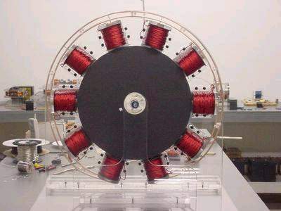
/HTML/20 Bedini_files/12 pole monopole.jpg)
12 Pole Monopole running
http://www.johnbedini.net/john34/Mono-Pole.mpeg
/HTML/20 Bedini_files/tbfnrganm.gif)
/HTML/20 Bedini_files/bedini 111.jpg)
John Bedini running a solid state radiant amplifier oscillator, Hendershot design
Books from Tom Bearden
/HTML/20 Bedini_files/tombearden1.jpg)
/HTML/20 Bedini_files/cover1c.jpg)
http://cheniere.org/books/FEG/index.html
The Attractions of Magnetism.
Could a Little Child be Leading Us into a Free Energy Future?
By Jeane Manning. Atlantis Rising, November 200(?), pg. 32..
The search for new energy technology takes us to northern Idaho to meet a ten-year-old girl who won a science fair with a battery-charging motor. She describes it as an advanced design that extends the life of batteries for an amazing length of time. The motor was designed by John Bedini and built by her. We meet him first.
More widely known as an audio-amplifiers expert, Bedini's name is intertwined with 'free energy' history. Witnesses saw his machines running successfully, but later others were unable to build devices according to his published instructions. His circuitry was mentioned favorably at a conference in Switzerland recently.
Aware of the controversies, with mixed feelings I drove into the Idaho panhandle, past a warehouse for survivalists' supplies. My hope is that he will give clues so others can duplicate his successes.
Explaining his theory about such devices, new-energy theorist Thomas Bearden is writing prolifically this year. Retired from electronic warfare studies and aerospace work, Bearden is the leading advocate of scalar potential electromagnetics, and he explains how the sea of energy we live in�an energetic flux of virtual particles�could be engineered to do work in the physical world.
Bearden also has a theory about another of Bedini's 'scalar' inventions--one which can increase enjoyment of music. After a six-year struggle, Bedini was granted US Patent 5,487,057 for a mechanism for reducing electronic distortion in digital and analog recording and playback. Bearden (writing in Explore Magazine Vol. 7, No. 4. pp. 53-63) says the patent examiner couldn't understand the mechanism, because Bedini's nonlinear optics process was not found in audio or classical electromagnetics textbooks. Meanwhile, John and his brother Gary were already selling the stress-defect-relieving devices. The process even works for media such as color film. Bearden explains Bedini's process as self-oscillating, optical electronics, and hopes that even standard metals can eventually be treated with it to reduce stress defects. Is this negative entropy--self-ordering in the physical world?
Bearden adds that most really now things are invented not by academic teams or corporate scientists but by the lone "independent fiercely creative people."
I meet Bedini at his business, surrounded by electronics equipment. The back room looks like a museum of small prototypes of unusual motor/generators. Some are pictured on websites http://rand.nidlink.com/John1 or http://johnbedini.net/john1/tesla.html
He says his knowledge is on the Internet, and now it's up to others to build the devices. He says they have to experiment themselves, and it reminds me that he taught a little girl how to make a motor which drove science teachers nuts�to see a little motor made of plastic with no return paths for the magnetics.
"The funny thing was that her father bent a coat hanger and put a coil above the motor and used it as a generator. The motor ran much longer under the load than they had expected."
John Bedini was roaming the "free energy" scene in California in the 1970s and early 1980s, collecting knowledge about medical as well as energy devices. He had an electronics business in Sylmar, and at home he experimented with windmills and other systems. The utility company objected�he was hooked up to their power lines and if his system were to backfeed, it could extinguish the lights in the neighborhood. He disagreed. As he tells it, the officials' final word was "we think you're stealing power" and they took their meter off the building. However, his lights were still on at night, because of his energy inventions, he tells me. Finally they struck a deal�he would have his power meter back but would pay a high fee for the service.
The power company almost took away their hookup to his shop, but it was in an industrial area and they would have had to remove a three-phase transformer and therefore deprive the other businesses of power. "They found that when they switched off all the power in the shop nothing (electrical) was being drawn, but the machines kept running."
He published instructions for an energy device which Jim Watson of Colorado Springs then built�large-scale with a heavy flywheel. Watson demonstrated it at the 1984 Bicentennial symposium celebrating Nikola Tesla's arrival in the USA.
/HTML/20 Bedini_files/Watson.gif)
At the same meeting Bedini displayed a circuit which charges batteries. Only one engineer out of the audience�Eike Mueller of the European space agency�got up and measured Bedini's apparatus. He affirmed that it was charging the batteries.
Dr. Hans Nieper's book Revolution in Technology, Medicine and Society states that Bedini's convener was 800% efficient in initial tests, and that 26 independent researchers successfully duplicated the device about which Bedini reported.
However, the staff of the no-longer-published magazine Energy Unlimited was unable to replicate the device, and consulting engineer George Hathaway criticized Mueller's measurements.
On the other hand, a presenter at the 1985 USDA conference, Ken Moore found that his model of Bedini's G-Field Generator increased speed as its load increased. He also witnessed a Bedini prototype successfully operating.
The same year, radio KABC talk show host Bill Jenkins used his guest speaker's spot at a March 12 Town Hall forum at the Biltmore Hotel in Los Angeles to announce a free energy device, with Bedini and Steven Werth. The two demonstrated what was described as a Kromrey gravity-field generator with 180% efficiency, powered by a battery bank which required no recharging from an outside source.
A newspaper account said the audience included public utility representatives and investment brokers. Bedini, then 37, told the forum that he planned to make his generator universally available to the public at a nominal cost, instead of selling to the highest bidder. He described his working model as using stressed pulsed scalar waves out of phase, to tap zero-point energy of the vacuum of space. The concept was not found in physics books, but is perfectly natural and it works, he said.
Jenkins had publicly introduced concepts such as scalar interferometry through one of his radio guests, physicist Bearden.
How did the civic officials at the Biltmore forum react to a "free energy demonstration�light bulbs strung across their luncheon plates? Bedini recalls they growled demands to remove the dam bulbs so they could eat. "Free energy" was not a part of their reality.
Within a few weeks, Bedini was visited by two thugs who were definitely unfriendly toward his efforts to unhook from today's power structures. They had the appearance of body-builders who had just stepped out of a gymnasium, and pushed him against his shop wall while saying in a threatening manner that they expect he will continue to use gasoline. He laughs shortly while recalling the incident, but evidently knew they were serious.
Now that he has moved to Idaho, the reason "they" don't bother Bedini any more, he figures, is that he limits his models to toy-size. His model collection only demonstrates a principle�that he believes could power a house if scaled up in size. The principle involves storing discharged pulses of energy that are created while doing work with previously stored energy. The sequence is "do the work, discharge, do the work, discharge" and so on.
The devices operate in a manner contrary to conventional motors and generators, I am told. "You want the thing to do work. The more work it does, the more energy it gathers: Bedini says.
A recent model, incorporating a bicycle wheel with magnets glued on the inside of the perimeter, has a large-bladed fan�angled to slow the rotation--as the work load. Bedini unhooked part of his circuit to demonstrate the spark. He was showing how much energy is sent back to the battery, continually in step. Repeatedly the setup runs the motor for a certain length of time, shuts it off and then discharges.
Bedini is scornful of experts who have visited him and can't understand why a small motor could be charging a battery yet the motor does not slow down.
"We understand what the energy is. Tesla knew exactly what it was. And it's the furthest thing from what they want to measure with their electron pushers."
Today's instruments all measure electron flow, he said, but no meters are available to measure what is involved in his models. What, then, is Bedini dealing with? It's electrostatic in nature, he replies, and must be converted into standard electricity.
The rhythmic pop, pop, pop sound of a Bedini device comes from a blue spark which he describes as an ultra-violet type of arc�-similar to radio-frequencies but not RF. It can be accumulated and discharged in pulses which then can be converted into electrons.
If scientists want to build a big electron-pusher, the answers are on his website, he said. However, Bedini has no patience with researchers who ask for specifics such as where to buy the magnets. "Just go get them. Don't bother me." He said the devices only need to be tuned, and exact materials are not crucial. "Use the type of magnets that fit your wheel. If you don't get enough output from the coils, and more windings. Or change the geometry."
I'll visit the little girl and see if it is that easy.
Earlier this year Shawnee Baughman wanted a science fair project. She found a book with plans for a motor, but it looked boring�corks and match boxes. Her father promised the parts for a better one. He works near John Bedini, who instructed Shawnee for a couple of hours a day for a few days. She finished building it the day before the fair.
"We only tested it for like a day, left it running overnight sometimes, but sometimes we'd leave it running for an hour or two hours or something."
The other kids liked it; that's how it was voted 'best of show'. Adult judges gave her the other top prizes.
She flicks the wheel, into motion and it runs.
"This is the electromagnet coil. It has the power wire and the trigger wire... The power wire carries the voltage around the electromagnet coil and it goes through to the transistor�that little black thing�then it goes through the resistor and the diode and the trigger wire follows it and then the voltage flow comes out again and returns back to the negative side of the battery... The electromagnet generates the power, then it spins the wheel; the electricity goes through the generator coil which lights up the light-emitting diode. Then it starts all over again."
"We've been using this battery for a month or so now. It's supposed to have only 900 spins per nine volts, and that's a nine-volt battery, so if it were to run out then it would have run out a long time ago!"
She has only changed the battery three times since building it six months ago.
Schools' involvement in the new energy field adds impetus. Andreas Manthey is an instructor who organized a Study Group for Free Energy at the Technical University of Berlin, Germany. He says the German version of my book impelled him back into new-energy research.
Jim Watson disappeared from the public new-energy scene a couple of years after the 1984 demonstration, but John Bedini and colleagues are sharing as much information as they believe that they can share. Bedini views children such as Shawnee as our hope for the future.
![]()
This proves that the energy can be stored in a capacitor then discharged to the secondary battery.
To see a school girl motor running and discharging into a light bulb, built by the real Harlen Sanders.
Go to johnbedini.net/john34/BediniMotor.wmv
/HTML/20 Bedini_files/atlris1.jpg)
/HTML/20 Bedini_files/atlris2.jpg)
/HTML/20 Bedini_files/atlris3.jpg)
The SG project building a six coil machine
johnbedini.net/john34/kron.html
![]()
TUV Test
BATTERY TEST FOR THE BEDINI
MOTOR GENERATOR
DATE : OCTOBER 13, 2000
BATTERY TEST SEQUENCE:
One lead acid gel-cell (12 volts, 450 milliamps) is being utilized as the primary source fully charged at 12.5 volts
Three (3) lead acid gel-cell batteries (12 volt, 450 milliamps) strapped in parallel are being used as the charge destination. The batteries are discharged to 10 volts for the test purposes.
Test #1 starts at 10:45 AM utilizing primary battery fully charged at 12.5 volts charging three (3) destination batteries paralleled. The destination batteries reach a charge capacity of 14 volts at 11:20 AM.
The destination batteries are then discharged to 10 volts under working load to prepare for Test #2.
Test #2 starts at 11:25 AM utilizing primary battery measured at 11.5 volts. Charging three (3) destination batteries paralleled. The destination batteries reach a charge capacity of 14 volts at 12:50 PM.
The destination batteries are then discharged to 10 volts under working load to prepare for Test #3.
Test #3 starts at 1:00 PM utilizing primary battery measured at 10.5 volts. Charging three (3) destination batteries paralleled. The destination batteries reach a charge capacity of 14 volts at 1:40 PM.
The destination batteries are then discharged to 10 volts under working load to prepare for Test #4.
Test #4 starts at 2:05 PM utilizing primary battery measured at 9.5 volts. Charging three (3) destination batteries paralleled. The destination batteries reach a charge capacity of 13 volts at 2:40 PM. The primary battery is now discharged to 9 volts under working load and unable to further run the
TOTAL BATTERIES CHARGED:
12 lead acid gel-cell batteries (12 volts, 450 milliamps each). This ratio is a 12 to 1 charging factor. The motor operation (work) being performed as this was done is not included as an additional factor in this test.
/HTML/20 Bedini_files/battest.gif)

/HTML/Bedini Discussion Forum_files/bedinisgintermediatebanner.jpg "Bedini SG - The Complete Intermediate Handbook")
/HTML/Bedini Discussion Forum_files/esm_header3.jpg "Energetic Forum") |
|
|||||||
/HTML/Bedini Discussion Forum_files/navbits_start.gif "Go Back")
/HTML/Bedini Discussion Forum_files/bedini-sg.gif "Bedini SG")
| John Bedini Discussion threads relating to John Bedini. Bedini SG, Bedini SSG, Crystal Batteries, etc... |
/HTML/Bedini Discussion Forum_files/reply.gif "Reply") |
|
|
LinkBack (1)
/HTML/Bedini Discussion Forum_files/menu_open.gif)
|
Thread Tools
|
/HTML/Bedini Discussion Forum_files/post_old.gif "Old") 04-26-2007, 11:55 PM
04-26-2007, 11:55 PM
|
||||
|
||||
|
Bedini SG Simplified
Bedini SG discussion here. For single or multi coil and/or multi strand. The simplified version to charge batts without the cap setup.
Get a copy of the only Authorized Bedini SG Handbook - Bedini SSG Last edited by Aaron : 11-25-2012 at 08:34 PM. /HTML/Bedini Discussion Forum_files/digg.gif "Digg this Post!") /HTML/Bedini Discussion Forum_files/delicious.gif "Add Post to del.icio.us") /HTML/Bedini Discussion Forum_files/technorati.gif "Bookmark Post in Technorati") /HTML/Bedini Discussion Forum_files/furl.gif "Furl this Post!") /HTML/Bedini Discussion Forum_files/live.gif "Live Bookmark this Post!") /HTML/Bedini Discussion Forum_files/google.gif "Google Bookmark this Post!") /HTML/Bedini Discussion Forum_files/yahoo.gif "Yahoo Bookmark this Post!") /HTML/Bedini Discussion Forum_files/myspace.gif "share on Myspace") /HTML/Bedini Discussion Forum_files/facebook.gif "Share on Facebook") /HTML/Bedini Discussion Forum_files/twitter.gif "Tweet this thread") /HTML/Bedini Discussion Forum_files/quote.gif "Reply With Quote")
|
/HTML/Bedini Discussion Forum_files/post_linkback.gif "1 links from elsewhere to this Post. Click to view.")
/HTML/Bedini Discussion Forum_files/user_offline.gif "Aaron is offline")
| Sponsored Links |
|
05-09-2007, 10:35 PM
|
||||
|
||||
|
John Bedini | Radiant Energy
|
|
06-14-2007, 12:52 AM
|
||||
|
||||
|
Aaron's SG
A Bedini circuit I built with a reel to reel motor John gave me
a few years ago. Pretty cool and interesting SG. Very fast and very efficient. Charges batts pretty good. I never measured efficiency. If I put 1 batt bank on the output or 4, it doesn't really change the input it doesn't care. Of course can grab the shaft to increase the load and the input does not increase. 5000 rpm it draws 1 amp avg 10,000 rpm it draws only 1/5 of an amp avg Video clip: http://www.esmhome.org/library/aaron...i/aaron-sg.wmv
|
|
06-18-2007, 08:38 AM
|
||||
|
||||
|
youtube video
|
|
08-17-2007, 04:14 AM
|
||||
|
||||
/HTML/Bedini Discussion Forum_files/icon3.gif "Lightbulb") Some musings...
Some musings...
@Kevin: I would strongly encourage you to do it an hour at a time if you have to, and please post progress reports!
/HTML/Bedini Discussion Forum_files/smile.gif "Smile") And yes, I've gotten bit by the high voltage coming off the power coil more than once! And yes, I've gotten bit by the high voltage coming off the power coil more than once! /HTML/Bedini Discussion Forum_files/wink.gif "Wink") Well, since I'm kinda stuck at the moment waiting for magnet wire to arrive before I can finish building the current machine, I thought I'd post a few thoughts on it--even though only one coil is present, it's got a diode hanging off the collector, so it counts in my opinion. /HTML/Bedini Discussion Forum_files/biggrin.gif "Big Grin") The schematic below shows its current state. The schematic below shows its current state.Yes, curiosity got the better of me and I've tried charging 1.5V AA cells as part of a 6V battery. It seems to work somewhat, though I haven't done any rigorous testing. I did notice that the rotor slows down when there's a battery in the charge position. Interesting! I know that you probably won't get optimum results using these types of cells, but it seems to me that if the negentropy process that Tom and John talk about in the provisional patent application listed in Free Energy Generation is correct, then it should be possible to charge these kinds of cells as well. Just a thought. Another interesting thing that I've seen (er, heard) with this machine is what I call 'the hum'. One time, before I soldered the components in place, I had to re-hookup the parts because they had wiggled loose. Once I had them connected back together and connected power (without a charging battery hooked up) I noticed a fairly loud hum coming out of the coil! The coil wasn't heating up and the neither was the transistor, but it pushed the magnets of the rotor out of the way so that the coil was in the middle of two magnets. Interesting! The hum stopped immediately as I disconnected the battery. After I connected power again, the hum started again. This time, I tried to see if there was anything coming off the diode but the meter reading was inconclusive. Strangest of all, when I connected a battery to the charging position the hum stopped as well. Curiouser and curiouser... After I disconnected the charge battery the hum didn't come back, but it did come back a while later. It seems to be a bit capricious, this hum. I did notice that it was much easier to get the rotor spinning up to speed when the coil was humming versus when it wasn't. It seems these machines are full of surprises. And maybe I didn't notice it before, but it seems that there's also a faint hum in the coil of the first machine that I built as well.A question comes to mind about this circuit. In the PPA in Free Energy Generation it's stressed that the radiant energy capture circuit has to be separated from the drive circuit, but in the circuit below, this is clearly not the case. Also, I have strong reason to believe that the circuit below works well (I can elaborate if necessary ), although some changes in the resistor are probably needed for optimum operation. It could be that I'm missing something obvious--after all, I'm still experimenting and learning this stuff first hand and trying to make sense of it all. /HTML/Bedini Discussion Forum_files/thumbsup.gif "Thumbs Up Smiley") Last edited by Shamus : 08-17-2007 at 02:33 PM. Reason: Forget something/typos...
|
|
08-17-2007, 04:27 AM
|
||||
|
||||
|
Shamus SG
Very Cool! Schematic looks good. Very nice bare bones ssg.
Those alkaline batts aren't the best but they can be charged at least a few times from my experience before having to throw them away. I'd recommend using some 6v and/or 12v gel cell batts...the black body type you can get at radio shack or elsewhere. Those are good to learn with. The hum you discovered is the circuit is self oscillating at high frequency. Most likely this is what is happening. If you have a scope on it, you will see something like this pic. /HTML/Bedini Discussion Forum_files/oscope.jpg) I played with my roller skate motor for months before doing anything else. Not even trying to charge anything with it. Will learn a lot more if you just get obsessed about the bare basic model first without doing anything else. In my opinion.
|
|
08-26-2007, 01:20 PM
|
||||
|
||||
/HTML/Bedini Discussion Forum_files/icon14.gif "Thumbs up") Preliminary results with big battery
Preliminary results with big battery
@Aaron: Thanks for the clarification. I think I've learned what I need to from the SG by itself--needless to say, there's probably more secrets in that thing than I've found so far. It continues to surprise me, especially in light of how simple it appears.
I'm sure you're probably aware of John Bedini's sense of urgency in wanting people to learn the technology (as expressed in this message). I have every reason to believe that he's right, and mostly from what I've been seeing from independent sources. The time is short. And I'm sure you'd agree that this isn't the place to discuss such things. At any rate, I've started some preliminary load testing, and the data so far is encouraging. Under the first load test, the battery took about 45 minutes to discharge down to 12.00V (under a 25W load running from a voltage inverter). Charging took about 30 hours to get it up to 13.46V (have to retune the thing for a PSU). /HTML/Bedini Discussion Forum_files/tongue.gif "Stick Out Tongue") Running another load test, the battery took about 60 minutes to discharge down to 12.00V under the same load. So there's something very interesting going on here. I'll post more details as testing progresses. Running another load test, the battery took about 60 minutes to discharge down to 12.00V under the same load. So there's something very interesting going on here. I'll post more details as testing progresses.
|
|
08-26-2007, 10:42 PM
|
||||
|
||||
|
conditioning batts
Hi Shamus,
Sounds like great progress. The capacity of your battery is growing as you condition them. You are literally changing the properties of the battery. Should grow in capacity and take less and less time to charge up to the same level. John has known the urgency for years but it isn't until recent times that people are paying attention. With gas prices going up and insane politics, people are starting to pay attention. The Bedini technology and water fuel cell technology are my two favorite ones to focus on.
|
|
08-30-2007, 04:16 PM
|
||||
|
||||
/HTML/Bedini Discussion Forum_files/icon4.gif "Exclamation") Latest results
Latest results
Well, I'm in round four of charging and things haven't been coming along as well as I had hoped. I'm not going to stop here until I see a solid trend, but the preliminaries thus far are not encouraging. That and the fact that it takes about 30-40 hours for one charge cycle!
/HTML/Bedini Discussion Forum_files/eek.gif "EEK!") Load times are staying fairly flat so far. Here's the numbers so far: Code:
Charge T  Chg End V  Ld St V  Load T
--------  ---------  -------  ------
                     12.85    00:44
32:50     13.46      13.34    00:57
29:48     13.47      13.36    00:48
40:20     13.89      13.52    01:03
/HTML/Bedini Discussion Forum_files/frown.gif "Frown") Now I've read where John Bedini says that the number of turns on the coil isn't important, nor its size. Maybe I'm getting some cross-conduction on my transistor (since it's 2N3055, which John considers junk)? I don't know how to check for that. John also says that you want the highest resistance on the base so that you get the highest RPM for the lowest current. Currently the RPM on my circuit is fairly high, and the base resistance is right around 1100 ohm. Now I've read where John Bedini says that the number of turns on the coil isn't important, nor its size. Maybe I'm getting some cross-conduction on my transistor (since it's 2N3055, which John considers junk)? I don't know how to check for that. John also says that you want the highest resistance on the base so that you get the highest RPM for the lowest current. Currently the RPM on my circuit is fairly high, and the base resistance is right around 1100 ohm.Anyway, I'll post more results as they slooooowly come in. NOTE: The missing data in the graph around hours 9-10 and 16-22 are due to an outside obligation at the time and the need for sleep. Last edited by Shamus : 08-30-2007 at 04:35 PM. Reason: Missing info... :-P
|
|
08-31-2007, 09:53 AM
|
||||
|
||||
|
will speed up
Hi Shamus, on these smaller systems, the charging will be much slower, but usually after many rounds of conditioning, the charging back up will get quicker and quicker.
A 5 coil setup (4 power 1 trigger) of about 18 guage 100 feet long each is for more practical application but before doing that in my opinion...getting the whole personality of the motor you have down is very crucial, in my opinion.
|
|
09-13-2007, 01:04 AM
|
||||
|
||||
|
After winding and rewinding several different coils, I have built one that I sort of like (for now). I had previously built a SSG with a 26+24 AWG so I used that as a base for a coil. On top of that I wound trifilar 20 AWG as power coil.
The motor works ok I suppose, what I'm wondering about is why do we need to tie all the multi-filar strands in the power coil together in parallel (for the circuit that does not have transistor per each coil)? When I keep them parallel I get about 100V radiant spikes, but when I tie them in series then I get little over 400V. Isn't it better to have higher potential? Are we looking for less or more resistance in the power coil? What about the trigger coil, should that be on a higher resistance? Also, the conclusion I came to is that 2N3055 is a joke compared to MJL21194 and that even for beginning circuits everyone should use the later. There's just a magnitude of quality difference between the two that cannot be ignored. My motor just purrrrs nicer with MJL21194 and can be fine tuned to a better degree than with 2N3055. Next I'm adding this Cap Pulse Timer circuit (link from Bedini_SG Yahoo group, I'd figure most of you are members there, no?) , has anyone else built this one and has any experiences to share? Oh forgot to add this. I built this coil and it worked (sort of because I did not wind to that size but smaller) but only if I pointed it in reverse (power coils toward the rotor). It was producing all kinds of strange sounds and would draw quite a current (1-2A sometimes). Somehow I could tune it down to 400mA and I'd get over 300V radiant spikes as well. Funny thing is that I have never seen my NE-2 bulb light up (dimly) when I touch the collector of the transistor on other setups except this one, and there was no primary or secondary batteries connected. /HTML/Bedini Discussion Forum_files/confused.gif "Confused") Is this normal behaviour and does it happen for you or did I stumble upon something unexpected? Last edited by amigo : 09-13-2007 at 01:14 AM. Reason: added more text
|
| Sponsored Links |
|
09-13-2007, 12:25 PM
|
||||
|
||||
|
Hola Amigo,
What is the difference between the 2N3055 and the MJL21194? I know the characteristics of the other parts (the 1N914 is a fast switching diode, the 1N4007 is a high power/voltage diode, etc) but when it comes to transistors I don't know squat. What are the characteristics that we're supposed to be looking for in this part? Power rating is one, but I have no idea what the others should be. If you don't know, maybe someone else who does can kindly interject.
|
|
09-13-2007, 05:07 PM
|
||||
|
||||
|
!!! Holy Smokes Batman !!!
Sometimes things just stare you in the face and you don't realize the implications until much later, when the connection finally manifests itself to you in a form so clear that you wonder why you didn't see it before.
/HTML/Bedini Discussion Forum_files/thinking.gif "Thinking Smiley") All of this arose because I was thinking of Rick Freidrich and the struggles he's gone through trying to convince people of what they had with the SSG. And the problem probably stemmed from the fact that most people don't have any understanding of conventional electronics theory--they just built the things, connecting the parts as shown in the schematic, and didn't really think all that much about it. So in the midst of pondering this, all of the sudden it hit me like a ton of bricks! /HTML/Bedini Discussion Forum_files/surprise.gif "Suprised Smiley") Take a look at the picture and circled part. The way the diode is hooked up means that absolutely no current will flow at any time according to conventional EM theory. The positive from the charging battery is blocked by virtue of being connected to the cathode of the diode coming off of the power coil! So simple! Yet so diabolically clever! The way that diode sits in the circuit (again, according to conventional theory) means that it's basically an open short--you could remove the diode and battery completely because they have absolutely no path where a current can flow through them! /HTML/Bedini Discussion Forum_files/rofl.gif "Rolling On Floor Laughing") After going through several charge/discharge cycles, you have to wonder just what is charging the battery? 'Cause it sure ain't electrons! Last edited by Shamus : 09-13-2007 at 06:23 PM. Reason: grammar, grmbl ;)
|
|
09-13-2007, 07:14 PM
|
|||
|
|||
|
Hi Shamus,
That diode does indeed pass current (and the more the better! :-). Think of it as a compression diode. When the transistor first turns on, the current from the battery is temporarily attenuated by the coil. Current will not flow until the magnetic field is built up around the coil. Consequently, when the transistor turns off, that field collapses and produces a high positive voltage right where the cathode of that diode is. If this voltage is not bled off, it will increase on subsequent cycles and blow up your transistor in many cases. It is this energy that is extracted buy the interaction of the magnet, coil and pulses that charges the battery so well. Voltage alone won't charge these batteries. They need a combination of high voltage and low impedance in short duration pulses. Note on batteries: Batteries take a while to become conditioned. Don't get discouraged if they don't work so great even through the first 10 or even 20 cycles. It usually doesn't take that long, but there are different types of batteries, sizes and chargers that make this an inexact science at best. None of the Bedini machines work that well on unconditioned batteries. That's one of the reasons I think people get discouraged. It also takes a while to get used to how the machines work. The SSG is an awesome machine for learning about this technology. The more you fool around with it and experiment, the more you will learn. It is a very simple machine electrically, but it embodies all the concepts Bedini has worked so many years to discover. It's all there for those who are patient and persistent. It just takes a while to learn. Ted
|
|
09-14-2007, 12:15 AM
|
||||
|
||||
|
has anyone ever tried to use AC on a bedini sg?
the reason i ask is that i wonder if you could use the wall current, and return it back to another outlet and reverse the Electric Meter outside. you would in a sense be "recharging" the electric company. in most states (in the US) they will pay you for power generated and sent to them. this would eliminate the need for 20 - 30 car batteries, noxious fumes, you could eliminate your electric bill, and possibly make some extra money on top of it. is this possible? -bryan
|
|
09-14-2007, 01:24 AM
|
||||
|
||||
|
In one of my experiments (now it escapes my mind whether I had that "weird" coil or was it a normal one hooked up - should start keeping lab notes, sigh) I used my DC power supply set to 12V as a primary.
I left the motor spinning and walk away from the desk for a bit. Came back and just looked around the desk then gazed up at the voltage indicator on the psu and it showed 16 or so volts. I was thinking what a ... so I unplug the motor and lo and behold the voltage went back to 12V. It would appear that the motor was feeding back some potential/energy back into the psu, while at the same time charging the secondary battery and spinning pretty fast. Sorry it's not directly AC related but I figured it might be relevant...
|
|
09-14-2007, 01:58 AM
|
||||
|
||||
|
i wouldnt be comfortable trying the AC experiment myself, as my electrical knowledge is old and rusty. i would be a bit nervous about doing major damage, shocking myself, or who knows what else.
i figured someone would have tried it by now, or at least thought about it.
|
|
09-14-2007, 06:28 AM
|
||||
|
||||
|
Charging batteries
Adam,
Since it is a cold charge there are no fumes generated when charging the batteries with the SG charger....batteries never get even warm. Aaron, correct me if I am wrong....but I believe the voltage spikes going into the battery are AC, not DC. (the neon light that lights up when it is running is a 120v ac light) Yes, Shamus, (Kevin hangs his head in shame- /HTML/Bedini Discussion Forum_files/embarrassed.gif "Embarassed Smiley") ) I am one of those guys that took the schematic, some explanation from Aaron, and some TRV data and just built it. Did not concentrate too much on how it worked...only as much as I need to in order to get the most usable energy for the energy spent. ) I am one of those guys that took the schematic, some explanation from Aaron, and some TRV data and just built it. Did not concentrate too much on how it worked...only as much as I need to in order to get the most usable energy for the energy spent.
|
|
09-14-2007, 12:15 PM
|
||||
|
||||
|
Kevin,
I think that the spikes are DC (basically PWM) - they are half-wave, rectified by the diode on the collector, no? The NE is before the diode thus it lights up only on AC. Someone please correct me if I'm wrong
|
|
09-14-2007, 04:39 PM
|
||||
|
||||
|
@Kevin: I was speaking mainly of the people on the Bedini_SG list who were demanding overunity from the machine without really comprehending what was right in front of their eyes, and Rick's frustration with said people.
At any rate, I'm just trying to figure out this stuff too since something seems to be very wrong with my setup. I'm in round 14 of load testing and the load times have been dropping about a 1/2 hour each time.
|
|
09-15-2007, 08:51 AM
|
||||
|
||||
|
sg and free spinning wheel
Hey Kevin,
Ditto to Ted's answer. Also, another thing to throw into the mix Shamus is that when the circuit is in resonance (you can usually hear and see the wheel speed up really quick like shifting gears), it is fast enough at that point that the "scalar south" between the north faces on magnets are ATTRACTED to the NORTH field on the coil pulse. At that time, the wheel is spinning for FREE! That is a good one to meditate on. The sg seems to only take power because there is back emf on the on pulse for a small blip of time and that is it. Before the circuit is in resonance (with rotor), it takes more power to charge an electromagnetic coil against a magnet with an opposing field. But a south field in between the norths actually helps pull that north field out of the coil easier! This is how I see it at least but no matter how it is seen, the wheel spins for free and the charging of the coil has it's own loss but that isn't what powers the wheel.
|
|
09-15-2007, 01:03 PM
|
||||
|
||||
|
thank you for the explanation, but that brings me back to my original question
has anyone ever tried to use wall AC current on the Bedini SG(battery charger version), and if it was possible to use this setup to send the power back to the electric company.
|
|
09-16-2007, 08:31 PM
|
||||
|
||||
/HTML/Bedini Discussion Forum_files/icon7.gif "Smile") Thank you!
Thank you!
Thank you Ted and Aaron.
As you know Aaron, once I got the thing functional with two circuits and started having a COP of 1.00+ I just concentrated on tuning it/experimenting to get the best COP I could. Shamus, Aaron or Ted or ?, may correct me, but if I recall I did NOT start seeing any significant COP of 1+ until AFTER my batteries were conditioned. This takes about 20-30 charge/discharge cycles. Another thing...I am sure it is because my wheel is not perfectly balanced, and because they are cheap bicycle bearings, but I found that the best RPM for my setup is between 295 and 300. I can get the RPM up to 900+, but when I do that the ratio of energy expended to energy captured in the charging batteries is not as beneficial COP wise. Of course, every setup is different. There are so many factors in tuning the charger-here is a list of just a few of the variables that I constantly played with: Resistance RPM Distance of magnets on wheel from coil Making sure all the wires from the coil to the different connections were the same length and as straight as possible. Experimenting with different gauge wire leading to the charging battery Getting the voltage spikes as clean as possible on the oscilloscope There is more, but those are the biggies that I can remember right now. Adam, regarding plugging into AC...that seems like oil and water to me...Aaron can correct me if I am wrong, but the energy "captured" by the SG is not able to be measured in a typical manner and is specifically usable by batteries. Oh Shamus, btw, I started out using the little gel cell 12 volt batteries from Radio Shack...everything worked fine on those, but I soon changed to full size deep cycle 12 volt batteries for the majority of my testing.
|
|
09-16-2007, 09:11 PM
|
||||
|
||||
|
@adam_ant: Like Kevin said, it probably won't work without doing something to transduce the hole current to an electron current. At any rate, it's certainly possible and people with solar and other more conventional overunity (err, COP > 1.0) systems sell excess power to the Electric Company all the time. If you do follow that course of action, you would do well to have a fake solar array somewhere just in case the Electric Co. comes snooping around. You don't want to mess with those guys.
@Kevin: Is what I have a gel cell? And how did you source your deep cell batteries? I do know that you can get them on the cheap if they're not new (and of course, that would be preferable), I just don't know where to get 'em.
|
|
09-17-2007, 03:25 PM
|
||||
|
||||
|
Shamus, that's a gel-cell.
I got mine from a surplus store though it's not 7Ah like yours but only 2.3Ah, for $1.95 each can't go wrong. Plus the battery seems brand new, plastic case looks pretty clean with just minor scrathes and the two connectors do not appear to have been used what so ever. Naturally I bought half a dozen...
|
|
09-17-2007, 11:30 PM
|
||||
|
||||
|
Most of my batteries are generic Walmart deep cycle and/or Marine batteries. I do have a couple car batteries that "died" and were discarded because they would not take a charge from a traditional battery charger.
After a couple dozen cycles on the SG they work like new!
|
|
09-18-2007, 02:56 PM
|
||||
|
||||
|
AC Schematic
Quote:
|
/HTML/Bedini Discussion Forum_files/abstract1.gif "gehko's Avatar")
/HTML/Bedini Discussion Forum_files/viewpost.gif "View Post")
|
09-18-2007, 10:40 PM
|
||||
|
||||
|
I'm not sure that simulation software can give us a real picture of the outcome. I thought that we are dealing here with "unwanted by-products" that most traditional engineers consider as noise and interference and want to surpress and filter out.
Software would most likely ignore it or discard it due to being based on convenitonal methods and beliefs, too? @adam ant What did you mean when you said to use wall AC current? Use it as a primary battery replacement, without any conversion to DC or just as a trigger?
|
|
/HTML/Bedini Discussion Forum_files/collapse_tcat.gif) LinkBacks (?)
LinkBacks (?)
LinkBack to this Thread: http://www.energeticforum.com/john-bedini/364-bedini-sg.html
|
|||
| Posted By | For | Type | Date |
| John Bedini | Radiant Energy | This thread | Refback | 05-10-2007 12:38 PM |
|
|
/HTML/Bedini Discussion Forum_files/collapse_thead.gif)
/HTML/Bedini Discussion Forum_files/goto_linkbacks.gif)
/HTML/Bedini Discussion Forum_files/linkback_url.gif)
/HTML/Bedini Discussion Forum_files/linkback_about.gif)
-
Jouni Sopanen
/HTML/Free Energy Step by Step Instructions Part 2 - YouTube_files/pixel-vfl3z5WfW.gif)
/HTML/Free Energy Step by Step Instructions Part 2 - YouTube_files/1.jpg) NoviSoul
NoviSoul
Guide new
-
Subscriptions
-
Bob42jh
4
-
RadioMillennium
-
SuperSmashBrosUK
-
EastPointPictures
-
CocoaHelsinki
-
FirstGenerationMusic
8
-
tibit77
-
ProjectMelee
-
tollopeloton1
3
-
breakingtheset
21
-
picturalia
57
-
Liquicity
4
-
Positive Money
1
-
DynamikOfficial
1
-
MusicFreeTage
28
-
majesticdnb
-
Google
-
Lombelicoelmondo
-
ssaaiixx
-
Resourcebased
-
GlobalResearchTV
1
-
TRUTHBOXNEWS
-
RP4409
2
-
Jonseredi
3
-
Globalfaction
7
-
erinsotherstuff
-
MrSuicideSheep
5
-
xansatsu
7
-
Verkkomedia JanusPutkonen
-
NateMusicTV
-
RolfTeneriffa
1
-
3ullet9roof
1
-
GoddessReawakening
-
TheSmashTeam
-
Geronimo Khan
-
RewdAdams
-
JohnnyHandsomeTV
-
MegaScraw
2
-
THELlGHT
-
djbonesandmr13
21
-
Liquify DnB
-
MissConceptions1
-
Deep Heads
-
SamaVene
-
newsoundera
-
TheSecularScience
-
ammoresperros
-
Undergroundspreader
-
m9hifidelitytv
2
-
mohammedyahyatv
-
chosenlogic
-
Shepard Ambellas
1
-
AkalaOfficialChannel
-
Phoenixdaicefire
3
-
freeDNBdotCom
2
-
KeiOrkkiatDubs
-
Formula4409
-
mountjarvis
1
- No channels found
-
-
![]()
![]()
![]()
![]()
-
/HTML/Free Energy Step by Step Instructions Part 2 - YouTube_files/default.jpg) 3:20 Free Energy step by stepby DeironesFeatured 1,636,939
3:20 Free Energy step by stepby DeironesFeatured 1,636,939 -
/HTML/Free Energy Step by Step Instructions Part 2 - YouTube_files/default(1).jpg) 2:06 Paul Scheerbart's Perpetual Wheelby veproject1 116,203 views
2:06 Paul Scheerbart's Perpetual Wheelby veproject1 116,203 views -
/HTML/Free Energy Step by Step Instructions Part 2 - YouTube_files/default(2).jpg) 0:34 Bedini Patent Animated ver. 1.0by MAllen7424 194,233 views
0:34 Bedini Patent Animated ver. 1.0by MAllen7424 194,233 views -
/HTML/Free Energy Step by Step Instructions Part 2 - YouTube_files/default(3).jpg) 2:51 Mini Tesla coil with 110v LED bulbby Lidmotor 362,541 views
2:51 Mini Tesla coil with 110v LED bulbby Lidmotor 362,541 views -
/HTML/Free Energy Step by Step Instructions Part 2 - YouTube_files/default(4).jpg) 25:17 Tesla's Earthquake Machineby mike44920 97,928 views
25:17 Tesla's Earthquake Machineby mike44920 97,928 views -
/HTML/Free Energy Step by Step Instructions Part 2 - YouTube_files/default(5).jpg) 4:39 Microdrones MD4-1000 behind the scenes (real live footage- not stabilized by software)by OrbitUAV 490,413 views
4:39 Microdrones MD4-1000 behind the scenes (real live footage- not stabilized by software)by OrbitUAV 490,413 views -
2:59 selfrunning free energy Kapanadze 10 kW generator on an islandby overunitydotcom 466,931 views
-
2:16 Bedini 12 coilby 1Robomaker 29,879 views
-
1:48 Perpetual Motion and Nikola Tesla (Tapping Infinite Energy)by debunkified 1,055,793 views
-
9:44 до "80%" экономии - это реально!by Юрий Тарасов 108,164 views
-
1:15 Free Energy " One of a Kind Device "by Lorrie Matchett 138,968 views
-
1:53 Free Energy Radiant Oscillator Lite Replicationby waterhouse24 104,565 views
-
6:11 How to speed up your internet speed 100000x faster (LATEST VIDEO)by mohammedzamin786 488,746 views
-
172 videos
Play all
Free- NR-Jah -Liberaby RedQueenWarrior
-
0:22 9V to 10KV inverter (spark igniter, stun gun, etc)by Radu Motisan 375,291 views
-
8:01 free energy video 5by HiddenIQ 1,009,133 views
-
4:11 Re : Magnets & Free Energy : You Can Make at Home Easily.by energyscience 899,308 views
-
3:03 Thermoelectrical Generator Kit - ThermoGenKitby exergiaDOTde 742,372 views
-
9:55 Bedini High Voltage Without D.C. Power Supplyby DadHav 1,741,563 views
-
0:37 Asymetric Magnet Motorby syncopetra 195,695 views
-
10:16 Wolna Energia - nowa technologia jest blisko: Randy Powell feat. Marko Rodinby wolnaplanetaPL 46,789 views
- Help
-
Jouni Sopanen
/HTML/Free Energy Step By Step Instuctions part 1 - YouTube_files/pixel-vfl3z5WfW.gif)
/HTML/Free Energy Step By Step Instuctions part 1 - YouTube_files/1.jpg) NoviSoul
NoviSoul
Guide new
-
Subscriptions
-
Bob42jh
4
-
RadioMillennium
-
SuperSmashBrosUK
-
EastPointPictures
-
CocoaHelsinki
-
FirstGenerationMusic
8
-
tibit77
-
ProjectMelee
-
tollopeloton1
3
-
breakingtheset
21
-
picturalia
57
-
Liquicity
4
-
Positive Money
1
-
DynamikOfficial
1
-
MusicFreeTage
28
-
majesticdnb
-
Google
-
Lombelicoelmondo
-
ssaaiixx
-
Resourcebased
-
GlobalResearchTV
1
-
TRUTHBOXNEWS
-
RP4409
2
-
Jonseredi
3
-
Globalfaction
7
-
erinsotherstuff
-
MrSuicideSheep
5
-
xansatsu
7
-
Verkkomedia JanusPutkonen
-
NateMusicTV
-
RolfTeneriffa
1
-
3ullet9roof
1
-
GoddessReawakening
-
TheSmashTeam
-
Geronimo Khan
-
RewdAdams
-
JohnnyHandsomeTV
-
MegaScraw
2
-
THELlGHT
-
djbonesandmr13
21
-
Liquify DnB
-
MissConceptions1
-
Deep Heads
-
SamaVene
-
newsoundera
-
TheSecularScience
-
ammoresperros
-
Undergroundspreader
-
m9hifidelitytv
2
-
mohammedyahyatv
-
chosenlogic
-
Shepard Ambellas
1
-
AkalaOfficialChannel
-
Phoenixdaicefire
3
-
freeDNBdotCom
2
-
KeiOrkkiatDubs
-
Formula4409
-
mountjarvis
1
- No channels found
-
-
![]()
![]()
![]()
![]()
All Comments
-
/HTML/Free Energy Step By Step Instuctions part 1 - YouTube_files/default.jpg) 9:55 Bedini High Voltage Without D.C. Power Supplyby DadHavFeatured 1,745,061
9:55 Bedini High Voltage Without D.C. Power Supplyby DadHavFeatured 1,745,061 -
/HTML/Free Energy Step By Step Instuctions part 1 - YouTube_files/default(1).jpg) 9:58 Physics of Free Energy Deviceby Eugene Jeong 336,881 views
9:58 Physics of Free Energy Deviceby Eugene Jeong 336,881 views -
/HTML/Free Energy Step By Step Instuctions part 1 - YouTube_files/default(2).jpg) 4:49 [www.witts.ws] Self-Running 40kW (40,000 Watt) Fuelless Generator (1 of 3)by wits2014 488,638 views
4:49 [www.witts.ws] Self-Running 40kW (40,000 Watt) Fuelless Generator (1 of 3)by wits2014 488,638 views -
/HTML/Free Energy Step By Step Instuctions part 1 - YouTube_files/default(3).jpg) 2:33 Free Energy - Evidence of military antigravity technologyby DoubleMarkez 390,020 views
2:33 Free Energy - Evidence of military antigravity technologyby DoubleMarkez 390,020 views -
/HTML/Free Energy Step By Step Instuctions part 1 - YouTube_files/default(4).jpg) 15:01 APEX 2013 SSBM L10 Shroomed VS CT EMP Mew2Kingby Jason AxelrodRecommended for you
15:01 APEX 2013 SSBM L10 Shroomed VS CT EMP Mew2Kingby Jason AxelrodRecommended for you -
/HTML/Free Energy Step By Step Instuctions part 1 - YouTube_files/default(5).jpg) 161 videos
161 videos/HTML/Free Energy Step By Step Instuctions part 1 - YouTube_files/default(6).jpg) Play all
washby dle3276
Play all
washby dle3276
-
2:59 selfrunning free energy Kapanadze 10 kW generator on an islandby overunitydotcom 466,931 views
-
1:53 Free Energy Radiant Oscillator Lite Replicationby waterhouse24 104,565 views
-
10:31 Pyramid Magnet - free energy - english subtitleby MrTermsof 616,081 views
-
4:11 My all new newman motor 1.(TheDaftman)by theDaftman 1,147,470 views
-
2:18 Is there free energy in magnets?by aetherix01 371,642 views
-
3:00 The Most Dangerous Video On The Internet - Trevor Paglenby killuminati63 585,755 views
-
2:18 Free Energy - Magnet Motorby ATBootstrap 358,641 views
-
2:38 100% free energy generator is easy to buildby LifeHack2012 238,092 views
-
1:48 Perpetual Motion and Nikola Tesla (Tapping Infinite Energy)by debunkified 1,055,793 views
-
4:11 Re : Magnets & Free Energy : You Can Make at Home Easily.by energyscience 899,308 views
-
3:41 5KW free energy бестопливный генератор Kapanadze Капанадзеby Alexander Frolov 488,213 views
-
3:29 Debunk this: FREE ENERGYby FreeCalamus 600,337 views
-
8:01 free energy video 5by HiddenIQ 1,009,133 views
-
10:03 Free Energy Generator and Overunity-John Searl and the Searl Effect Generatorby SupremeMasterTV 560,004 views
-
2:37 Overunity free energy generatorby Deirones 349,331 views
- Help
Home
See New
Mini-Romag Data � click here
Mini-Romag Generator

Mini-Romag Generator (PDF 260KB)
Mini-Romag Generator CAD cut-away (.dwg 704KB)
Mini-Romag Generator CAD Rotor (.dwg 186KB)
Mini-Romag Generator CAD (.dwg 781KB)
- Generator runs on free energy provided by
magnets and the earth's energy field
- Generator produces magnetic current
equivalent of 3-1/2 volts and 7 amps
- Generator requires startup of 2100 RPM for
42 seconds
- Suggested use for generator: charging
magnetic battery, powering small magnetic devices like a magnetic water
pump
- Generator does not produce pollution
- Generator is designed to recycle magnetic
energy back to help save environment
- Materials necessary to construct generator
are readily available
- Generator requires a load to maintain
continuous operation
We are providing this
free information out of love to help save our planet. Please help us in
educating people about magnetic energy.
ABSTRACT
This
generator is a magnetic device incorporating the use of permanent magnets
turning with a rotor to generate a magnetic energy which is then circuited to
other mechanisms to do useful work. This mini generator demonstrates that
magnetic principles can be utilized in units of various sizes. Magnetic units
can be microscopic or a mile wide, as long as the correct principles are
maintained. When magnetic fields are properly harnessed, when the magnets and
housing are a certain composition, when the magnets are rotating at the proper
rpm, and when the energy is given a redistribution path, a very powerful
phenomenon occurs; the natural flow of Universal magnetic energy begins to
escalate. All magnets draw energy in to maintain their power, but under the
right conditions magnets can assist in attracting large quantities of magnetic
energy that can be used for numerous purposes.
It
is critical to remember that this magnetic generator does not create pollution
while it is running. The conventional processes used to obtain the materials
obviously create pollution, but as people progress beyond the current
destructive technology, even the processes of extracting natural resources and
manufacturing materials will become less polluting. It is also critical to note
that this device is designed to recycle the energy it uses from the Earth's energy
system. Scientists will soon come to a consensus that electricity does not
properly harness the natural flow of energy and that the electrical power
system does not properly recycle energy after it is used. The environment is
suffering because of current technology, especially electricity, and it is
becoming critical that people begin to switch to a new form of energy
production.
Many
of the negative effects of electricity production are apparent to most people,
the stripping of natural resources and the millions of tons of pollution that
power plants pump into the atmosphere. But the Earth's system is being severely
affected by critical energy interaction that is occurring between electrical
fields and the magnetic field around the planet. The focal point of
electricity's negative effect on the environment occurs in the ionosphere. The
ionosphere is a sea of pulsing neutrons that assists in sustaining life on this
planet. The ionosphere supplies the energy for any system in the environment
that requires energy to function. Power planets are constantly drawing energy
from the ionosphere to maintain functioning. The problem is the power plants do
not use the energy properly, nor do they recycle the energy back to the
ionosphere. Running power plants create an imbalance in the Earth's energy
field that causes the ionosphere to perform a rebalancing process. Powerful
vortex fields form in the ionosphere that draw energy up to restore the
depleted field. These vortex fields often result in dangerous storms that
involve tornadoes and hurricanes. The H.A.A.R.P. Project (High-frequency Active
Auroral Research Project) in
Nikola
Tesla had a firm understanding of the interaction the ionosphere had with
energy systems. Tesla designed many devices that form the foundation of today's
technology. Tesla also invented magnetically based devices that were never
produced in large quantities that were far superior than today's technology.
Through his research on magnetism and electricity, Telsa repeatedly
demonstrated how intricately the energy fields we generate are connected to the
ionosphere. Telsa also proved over and over that weather can be influenced by
artificially generated energy fields. For decades, the government has been
using Tesla's concepts to test and abuse the ionosphere without regard for the
environment and the safety of people.
It
is critical that people stop damaging the ionosphere with electricity, not only
because the weather will become increasingly severe, but because ozone holes
are continuing to form and expand. Chemicals have never been the cause of the
ozone holes. Electricity production is the primary cause of the ozone holes,
and many scientists have known this for many years. It is an electrical
interaction that is altering magnetic molecular structures preventing a natural
restoration to the planet's energy field that is creating the ozone holes. The
process forming the ozone holes will be stopped because without the ozone
layer, life will cease to exist on this planet.
The
time will come in the near future when the Earth will undertake a pole shift
that will alter the magnetic field around the planet. This pole shift will make
electricity generation impossible. The ionosphere will no longer supply the
energy structures that make it possible for power plants to generate electricity.
This pole shift will force people to use different technology, like magnetic
energy, to power devices. The revelation of a pole shift and the changing
magnetic field is being given to many people, and it is a necessary process for
the Earth to undergo to begin the process of healing, or rebuilding the energy
field around it to ensure a stable, long lasting system. Magnetic technology
will assist in rebuilding the system and ensuring our long term survival.
PRINCIPLE
BEHIND THIS ENERGY SOURCE
This
generator utilizes neutral magnetic energy from the Earth's energy field by
attracting the energy through the proper magnetic harmonic. The unit captures
the energy and changes it into a polarity that magnetic devices can accept.
This simple unit is like a water wheel, it only functions if a flow is moving
through it, and it will continue turning as long as it is being used to power
something.
An
important object of the present device is to provide a revolutionary new
concept concerning the utilization of power by directly capitalizing on the
natural resource of magnetism. Electrical power is the result of expending
energy to drive a copper wire through a magnetic field. But magnetic energy is
a natural resource needing a specific mechanism to draw on. There is no
incorporation of a secondary energy source except at start-up, to cause this
magnetic generator to continuously function.
HOW
THE UNIT FUNCTIONS:
The
here disclosed 31/2 volt, 7 amperage magnet motor/generator must be charged up
by driving the main shaft at 2100 RPM for 42 seconds. This charging process
manifests as magnetic energy within the six coils of copper wire, the copper
tube supporting these coils and the copper coated steel wires wrapped around
the magnets. This charging is accomplished while the six coil connection
wires, Part #22, are making contact and setting up their alternating
magnetic poles. After the 42 second charging time one of these coil connection
wires must be opened and this circuit again completed through an energy draw at
what could be called 7 amps. See load Part #23. As current is drawn from the
six coils, this draw sets up magnetic poles which are a response between the
rotor magnets and the coils. This response then causes the main shaft to be
rotated by the 12 permanent magnets as they attract and build a release field.
Then the driver unit (hand crank) is disconnected allowing the unit to rotate
with the load being the activating driving force.
The
fields of the magnets must be maintained during their spin movement. These
magnetic fields which are encapsulated are achieved by the wiring system. The
attract/release of the magnets is a function of several factors. First, the
magnets attract field between north and south is completed by taking a crossing
path of attract (top of one row to bottom of next, etc.). This action has the
effect of fields blending into fields, and a hold-back attract does not happen.
Each time a magnet set passes a coil an interchange of like energy between the
coils around the magnets and the generating coils sets-up neutral polarities
which are 'release fields' and prevents a hold-back attract.
One
important magnetic assembly is the circuitry which allows this interchange of
energy. This is a recycling of a stabilized magnetic energy not electro/magnetic
because the field of force is not a case of electrical input, an input that
created the magnetic energy, but rather a build-up of magnetic energy which
caused an energy thrust.
In further
defining the workings of this unit it is important to understand that although
electrical and magnetic (energy) work with similar attitudes, the manner
in which they work sets-up a differing energy effect. One of these effects is
that magnetic structures want to share their f1ow, compatible to the
Universal Force, while electrical flow argues, (short circuits, sparks, etc.).
Because of this fact the working responses (within the unit) take place, how
they are needed, and when they are needed which results in a functioning unit.
There is a continuous transmutation process taking place whereby magnetic
energy continually generates an energy that manifests a measurable
current.
In
the past, inventors have sent devices and drawings to Patent Offices claiming
they had invented perpetual motion. This motor, which is driven totally by
permanent magnet power, in no way can be compared with perpetual notion in that
the principle is not the same. When perpetual motion is discussed, it is
mentioned in terms of unknown factors which produce an unknown force. Here, in
this Mini Ro-Mag, the force of attract-attract to attract-release within the
magnetic structure can be observed, thereby producing the generating force to
turn the rotor which in turn produces the outflow of power. This power source
is not predicated on a continuous flow of energy but predicated on the
consistency of the transmutation process of the magnetic molecular structures
within the Earth's pressure flow.
Some
additional points may be useful in understanding the functioning of this unit.
The thin web of brass between the magnets is important because it acts somewhat
like a magnetic insulator. Each section of brass, on the sides of the magnets
becomes charged, somewhat like a capacitor. This builds into a force which
TAKES PART in causing the rotations.
The
magnets have a particularly low charge, but their charge is only a catalyst at
the onset. It is during the SPIN charging that this blend of alnico elements
draws neutral magnetism from the atmosphere that then manifests with the proper
magnet strength for continuous running. This 2.2 peak energy product is the
power needed that becomes a point of INCOMING and OUTGOING magnetic
transference. Too much charge would solidify polarities that would then negate
the needed VARIETIES of DIFFERENT magnetic fields.
This
Mini-Romag generator cannot run horizontally. The magnetism of the earth system
FEEDS this unit from the top. Gravity is compressed magnetism. The spinning
rotor CAPTURES this compressed magnetism.
Without
the copper coated steel wire around the magnets no activity
would take place and here is why. As the rotor is spun, an action that MUST
happen is that the fields around the magnets need to stay with the magnets.
These fields do not manifest as individual flux lines if the magnets are not
wrapped as disclosed. The copper-coated steel wire becomes a MAGNETIC
CONTAINMENT FIELD as these wires take on THEIR OWN charge. These SETUP fields
then serve as ISOLATOR fields which keep the magnets' flux lines in their
place.
The
reason these copper-coated steel wires need no insulation is because the COPPER
COATING ITSELF builds into a magnetic flow, which insulates the
primary flow that travels inside the steel portion. This action results in a
magnetic flow circuit that is GUIDED by the activity of the copper coating.
This action should serve as a TEACHING to show how magnetic current can be sent
through conductors that are TOTALLY UNLIKE the standard electrical insulators.
The primary USE of this field (set up by these wires) is that it serves as a
RELEASE AGENT that breaks the elastic hold-back during the generating cycle.
The
reason for the U-bent wires is that they serve as a CONDUIT that causes the
magnets flux lines to take their travel path very close to the magnet. This
circuit path is around the back surface and both side edges. This action can be
likened to compressing a balloon. The result is that the field on the front or
WORK SURFACE is greatly extended OUTWARD. This outward extension impacts the
copper stator core, which then FEEDS captured magnetic current into the stator
windings.
SUBJECT: Answers to
questions about the Mini Romag unit
To be successful, we
must all put our energy into making this work. We were given this information in
bits and pieces that we had to sort through to make sense of. There may still
be improvements to the design we have presented. For example, the romag may
contain information useful on the miniromag - we have not done enough
experimenting to see if this is true.
Q1) What type of brass
is used for the rotor?
A1) brass rotor made of
83% copper, 3% Zinc, 7% Tin and 7% Lead. This info is taken from the romag.
Q2) About the 12
permanent magnets on the Mini-Romag, is the Alnico 4 material and its charge to
only 2.2 peak energy product important?
A2)The 2.2 peak energy
product is critical even though it produces magnets that are VERY WEAK. The
magnet company we used said their most difficult part of making these magnets
was to charge them FAR LESS than their energy potential. It seems these magnets
and their charge are at the very heart of this unit�s design. We had a teaching
about the need for controlling the release timing in order to make a magnet
motor. This teaching states, "the release timing in magnets is dependent
on their strength. "A magnetic current needs to be free to flow TO the
rotor, then away from it, as the magnets charge and discharge their energy. The
release timing is the key to this activity.
Q3) Is there insulation
on the outside surface of the copper coated steel wires?
A3) We don't think so,
although we haven't tried the unit with insulation on the wires.
Q4) Should the 11
(eleven) turns of copper coated steel wire be connected to something?
A4) Yes, the drawings
show the upper six magnets have these wires connected in series. The lower six
magnets are also connected in series, but there are no connections from the
upper to lower rotor magnets. The flow inside the wires is encouraged to flow
around by connecting the wire that exists at the SOUTH half of the magnet to
the wire located at the NORTH half of the wire next to it.
Q5) What is the primary
reason for using these copper-coated steel wires around the magnets?
A5) During the spin
mode, the method for containing the magnetic power of each magnet is to wrap
them as stated. When the rotor is spun and charged, these wires serve a
critically important function as CONNECTIVE DISTRIBUTORS. They distribute an
energy flow by properly containing the magnetic power of each magnet, and at
the proper pulse point release a harnessed energy into the stator winding.
Q6) What keeps the
magnets from flying out?
A6) The wrapped magnets
fit snugly into the bent wires. We are not sure of the best way to mount them,
we just applied a thin coat of clear 5-minute bonding agent on to the bent
wires. As we rotated the rotor at high speed, we never had any magnets come
flying out. There may be another method of mounting the magnets that produces
greater output, we just don't know yet.
Q7) Did you bond the
Mica into the slots?
A7) Yes. As you probably
know, Mica cracks if you bend it at room temperature. So we first cut the mica
to size then heated it with a standard iron. Next, the rotor was pre-heated to
about 200 degrees F. and the soft Mica was placed onto a heated tool the shape
of the slot. Next a bonding agent was placed in the slot area and the tool
forced the Mica in place, allowing it to stay until the bonding agent was set.
Q8) Can some other
insulation be used instead of Mica?
A8) The Mica is not just
for insulation, it serves an important magnetic function by setting up needed
fields of energy. Thus Mica is very important.
Q9) How can the
Mini-Romag take a load with the use of only one bearing?
A9) This Mini-Romag unit
is not intended to drive ANYTHING. Its value is that it produces useful
magnetic current. The shaft is used only to drive it at start-up with an
IN-LINE coupling.
Q10) How many light
boxes will it light up?
A10) NONE. The drawings show
that only the light box generator can light up light boxes. It seems the best
application for this unit is to feed magnetic current to a small Magnetic
Heating Unit, a Magnetic Water Pump, or some other small magnetic device that
will attract magnetic energy.
Q11) What does it mean
that the rotor magnets have a changing magnetic spacing?
A11) The face of the
magnets, which is directed toward the stator coils, is a flat surface. The coil
has a rounded surface. As the lead and trail edge of each magnet pass any coil,
the center part of the magnet maintains a distance from the coil which is
farther away. This action causes different surfaces of the magnet to REACH to
the coil with changing sizes of flux lines. This changing magnetic spacing
contributes to the generated flow that leaves the coils. How do we know? We
asked if a thicker magnet should be used then rounded to fit the radius of the
winding, and the answer was NO.
Q12) Can the Mini-Romag
run horizontally?
A12) No. The feeding of
magnetized molecular structures must enter from the top of the unit.
Q13) Is it possible to
use a 3-volt light bulb as a load for the Mini-Romag?
A13) The first items we
tried were small light bulbs. Electrical devices do not DRAW magnetic current
because they do not have an attract structure. Neutral magnetic current must be
offered a place to go which offers it a chance to gain a particular polarity.
There may be a way to modify light bulbs to get them to work with this unit, we
simply do not know yet. The principles of the pump and the magnetic motor might
reveal a way to set up a magnetic circuit and device to draw magnetic current
into various devices. To learn more about this subject study the action of the
10 HP Magnetic Motor and the Water Pump.
Q14) Is the Mini-Romag
going to run by itself if one does not open the starter switch to draw off
magnetic current?
A14) No. The six coils
need to setup attract poles to the spinning rotor. It is only when magnetic
current is removed from the coils that they establish their needed poles.
Q15) Would a
copper-coated steel wire having a coating of solder do for wrapping the wires?
A15) We don't think so,
solder, for some reason, was not even to be used on the connections.
Q16) The coils wound
with the stated turns on the Mini-Romag stator do not add up to the sizes
given. Why not?
A16) We probably should
not have given coil sizes, just the number of turns. However, we found these
coil sizes by actually measuring our coils after winding. All our work was HAND
WOUND and it is the human element that adjusts what is possible to what theory
says should be the finished sizes. It was a tight fit, but it did fit
nevertheless. Maybe reducing the number of turns until the coil fits is the
easiest solution.
Q17) Was the acrylic
dome just for protection against the weather?
A17) Probably not. Other
magnetic units needed to have the air space around them CONTAINED so that the
air could be magnetically charged. As we spun our unit, waves of magnetic
energy could be felt several inches away from the stator.
Q18) Are the mounting
points for the copper stator actually rivets that fit into the acrylic ring?
A18) No. The six copper
downward extensions should go � inch deep into the aluminum base plate. The
purpose of the aluminum base is to feed a magnetic charge into the copper
stator. We had difficulty mounting this stator as directed and mistakenly added
the acrylic ring, one of the errors we later found by looking at old notes.
Q19) Would you be
interested in building another Mini-Romag or finishing the 50 HP Romag if help
were forthcoming?
A19) Our experience with
this free energy subject has been nothing but massive suppression. When we have
the freedom to actually make these units without threatening the present fossil
fuel based economy, we will proceed with construction. At this time, we are to
teach about magnetic energy. We have asked, "So when can we have the
freedom to build and use some of these great devices?" The answer we
received was, "Don�t get ahead of me, just don�t get ahead of me, the
timing must be perfect." That answer seems to guide our next step. We will
know when to GET TO WORK.
PARTS
LIST AND CONSTRUCTION DETAILS
When
building your first unit we suggest using the stated materials.
1)
Aluminum Base Plate
2)
Sleeve Bearing, 1" long, 1/2" inside diameter, oil impregnated brass.
3)
4" long by 1/2" diameter Brass Shaft
4)
Brass 2" diameter Rotor, 1-3/4" long
5)
Six rotor slots, each 1-3/4" long by .260 deep by 23/32" wide. These
slots are spaced exactly 60 degrees apart.
6)
One slot cut in center of Brass Rotor, 360 degrees around, 1/4" wide by
5/16"
deep.
7)
12 slots (formed from the six slots as the 360 degree cut is made). Each slot
is lined with .010 thick mica insulation.
8) A
total of 228 pieces of U-shaped .040 thick copper coated steel wires. Each slot
(Part #7) has 19 pieces of these wires fitted into the Mica, thus these wires
do not contact the Brass rotor. The lead edge of these wires (See Figure 7) is
flush with the Rotor's outer surface and the trail edge protrudes 1/8"
above the Rotor's outer diameter.
9)
Eleven complete turns of .032 thick copper coated steel wire. These 11 turns or
'wraps' accumulate to 3/8" wide and the same pattern is placed around all
12 magnets. When placed into the bent wires #8, they are a snug fit making firm
contact.
10)
Are 12 pieces of .005" thick mylar insulation inserted into the cores of
the wires #9.
11)
12 permanent magnets, insulated with the mylar, to not contact wires # 9. These
magnets measure 3/4" long, 5/8" wide, 3/8" thick
and are made of a special composition and strength. Alnico 4, M-60; 12 AL, 28
Ni, 5 Co, bal Fe, Isotropic permanent magnet material cooled in magnetic field,
Cast 9100 TS. 450 Brin, 2.2 Peak energy product. When inserted in the rotor the
outer faces of these 12 magnets are not to be machined to a radius. The center
of these magnets pass the center of the coils with 3/32" clearance. The
edges, where the wires are wrapped, pass 1/32" away from the coils. This
'changing magnet spacing' aids in not only the release cycle but also
contributes to rotational movement. (Sharp magnet edges which are facing the
coils are to be sanded to a small smooth radius.)
12)
Magnet polarity placement into Rotor. (See Figure 5.)
13)
Connection pattern for wires wrapped around magnets. (See Figure 6.) The 12
wire wraps are divided into two sections, upper and lower of six each. There
are no connections between these sections. The magnetic flow direction between
the upper 6 wraps and the lower 6 wraps is attained by the 'flow direction' as
shown in Figure 5. Viewing Figure 6 shows the wires wrapped around the magnet
starting at the top 'north' half and then after 11 complete turns the wire
exits at the lower 'south' half. As this wire then goes to the next magnet it
arrives at an attract wire which is its 'north' side. Thus all wires get
interconnected from south to north magnet half or north to south magnet half.
The actual connections should be crimped copper clips not solder with
insulation tubing to prevent contact to the Rotor body.
14)
A .030 thick copper tube (stiff material) 2" long by 21/2" inside
diameter.
15)
Are six slots cut at the top of tube #14. These slots are 5/8" wide by
1/32"
deep spaced at 60 degrees apart.
16)
Are six slots cut at the bottom of tube #14. These slots are 5/8" wide by
5/16" deep and in line with the upper slots #15.
17)
Six copper tube mounting points.
18)
Acrylic ring to hold Part #14, measuring 3-3/4" O.D., 21/4" I.D.,
3/8" thick bolted directly to Part #1. This ring has a .030 wide groove
cut 1/4"deep to allow the six copper tube mounting points, Part #17, to be
inserted.
19)
A .002" thick plastic insulation paper to be placed around the inside and
outside of Part #14.
20)
Are six coils of insulated copper wire, each coil having 72 turns of .014 thick
wire. Each coil is wound with two layers, the bottom layer to completely fill
the 5/8" wide slot with 45 turns and the top layer to span 5/16" wide
with 27 turns. To be sure each coil has the exact wire length or 72 turns, a
sample length wire is wrapped then unwound to serve as a template for six
lengths. A suggested coil winding method is to fill a small spool with one
length then by holding the copper tube at the lower extension, then start at
the plus wire in Figure 2 and temporarily secure this wire to the outer surface
of the tube. Next, place the pre-measured spool of wire inside the tube,
wrapping down and around the outside advancing clockwise until the 5/8"
slot is filled with 45 turns. Then, return this wire back across the top of the
coil for 15/32" and winding in the same direction again advance clock-wise
placing the second layer spanned for 5/16" with 27 turns. This method
should have the second layer perfectly centered above the first layer. After
winding this coil, repeat the process by again filling the small spool with
another length of pre-measured wire. A very important magnetic response happens
as all six coils have their second layers spaced as disclosed.
21)
This number identifies the top view of the second layer.
22)
Connection pattern for six coils shown in Figure 2. When the unit is driven at
start-up (hand crank) for 42 seconds at 2100 RPM, all six jumper wires must be
together which means the plus wire goes to the minus wire connected by the
start switch. After 42 seconds the load is added to the circuit and the start
switch is opened. To double check your connections between the coils, note that
the finish wire of coil #1 goes to the finish wire of coil #2, which is top
layer to top layer. This pattern then has start of coil 2 (bottom layer) going
to start of coil 3 (also bottom layer). When the copper tube with the coils is
placed around the rotor, the distance from any magnet to any coil must be
identical. If it measures different, acrylic holding shapes can be bolted to
the aluminum base, protruding upward, and thus push the copper tube in the
direction needed to maintain the spacing as stated.
23)
Wires to load.
24)
Wires to start switch.
25)
Rotational direction which is clock-wise when viewing from top down.
26)
Acrylic dome for protection against elements.
27)
Coating of clear acrylic to solidify rotor. Do not use standard motor
varnish. Pre-heat the rotor and then dip it into heated liquid acrylic.
After removal from dip tank, hand rotate until the acrylic hardens, then
balance rotor. For balancing procedure, either add brass weights or
remove brass as needed by drilling small holes into rotor on its heavy side.
28)
Insulation tubing on all connections.
29)
Shaft for start purposes and speed testing (if desired).
This
concludes the parts list for the Mini-Romag. Please share this information with
others.
/HTML/Magnets 4 Energy - Testimonials._files/loading.gif)
/HTML/Magnets 4 Energy - Testimonials._files/close.gif)
|
|||
/HTML/Magnets 4 Energy - Testimonials._files/footer.jpg) |
|||
/HTML/Magnets 4 Energy - Testimonials._files/line_foot.gif) TestimonialsFAQTerms & DisclaimerReport SPAMAffiliatesContact Us TestimonialsFAQTerms & DisclaimerReport SPAMAffiliatesContact UsCopyright 2013 Magnets4Energy.com, All Rights Reserved |
/HTML/Magnets 4 Energy - Videos_files/loading.gif)
/HTML/Magnets 4 Energy - Videos_files/close.gif)
/HTML/Magnets 4 Energy - Videos_files/footer.jpg)
/HTML/Magnets 4 Energy - Videos_files/line_foot.gif)
/HTML/Magnets 4 Energy� - The Bedini Generator in Action_files/loading.gif)
/HTML/Magnets 4 Energy� - The Bedini Generator in Action_files/close.gif)
| The Bedini Generator in Action Click To Go Back |
/HTML/Magnets 4 Energy� - The Bedini Generator in Action_files/footer.jpg) |
/HTML/Magnets 4 Energy� - The Bedini Generator in Action_files/line_foot.gif) TestimonialsFAQTerms & DisclaimerReport SPAMAffiliatesContact Us TestimonialsFAQTerms & DisclaimerReport SPAMAffiliatesContact UsCopyright 2013 Magnets4Energy.com, All Rights Reserved |
/HTML/New Page 2_files/magneticenergysecretsbanner.jpg "Magnetic Energy Secrets by Paul Babcock")
The SG Project
/HTML/New Page 2_files/bigguy1.jpg)
/HTML/New Page 2_files/medbig.jpg)
I will be posting new pictures as the building process on the new energizer moves along.
/HTML/New Page 2_files/machtherot.jpg)
Machining the rotor
/HTML/New Page 2_files/finish rot..jpg)
Finished Rotor 6' Diameter
/HTML/New Page 2_files/coilmac..jpg)
Machining coil mounts
/HTML/New Page 2_files/coilmounts.jpg)
Finished Coil Mounts
/HTML/New Page 2_files/templatepat.jpg)
Making the template for the bearings
/HTML/New Page 2_files/closeuprot.jpg)
Close up view after bearings are installed
/HTML/New Page 2_files/sideviewal.jpg)
Side view alignment
/HTML/New Page 2_files/frontviwe11.jpg)
Marking angle alignment of rotor
/HTML/New Page 2_files/magaling1.jpg)
Rotor mounted with magnets and aligned
/HTML/New Page 2_files/frontmount.jpg)
Front view of rotor with magnets
/HTML/New Page 2_files/coilwind1.jpg)
Winding the coils on the coil winding jig
/HTML/New Page 2_files/rods11.jpg)
Cutting welding rod for coil cores
/HTML/New Page 2_files/coilready2.jpg)
Coils wound and mounting bases finished
/HTML/New Page 2_files/gluecoil1.jpg)
Coil being glued to mounting base under pressure
/HTML/New Page 2_files/coilmotmont1.jpg)
All six coils mounted on frame around rotor
/HTML/New Page 2_files/coilsidev1.jpg)
Angle view of finished mechanical set up
/HTML/New Page 2_files/switchingmount1.jpg)
Mounting the switching circuits.
/HTML/New Page 2_files/coleswitching33.jpg)
Soldering switching circuits to the coils, mounting buss bars.
/HTML/The Mini-Romag explanation _files/mromag.gif)
The Mini-Romag generator
Towards a possible explanation ?
by Jean-Louis Naudin
Created on 04-08-99 - JLN Labs - Last update 04-13-99
/HTML/The Mini-Romag explanation _files/mromag1.gif)
The Mini-Romag generator
from Magnetic Energy is composed of two main parts : The
Rotor and the Stator.
- The Rotor is a brass cylinder with 6
pairs of magnets placed at 60� around its circumference. The
magnets polarities are alternatively North and South.
- The Stator is a copper cylinder with 6
flat coils wounded so as the coils axis are tangent to the
rotation of the rotor. So, only the orthogonal component of the
magnetic field of the magnets is used.
The oscilloscope pictures below, show the signal
generated by a moving magnet :
- The left picture
is the voltage generated across the coil when a magnet axis
crosses the coil axis, this is a conventional setup for a
magnetic generator.
- The right picture is the
voltage generated across the coil when a magnet axis crosses the
middle of the tangent coil (orthogonal component of the magnetic
field), this is the case of the Mini-Romag generator.
/HTML/The Mini-Romag explanation _files/magconfig.gif)
In the left case (conventional generator), you can notice that the signal induced across the coil is symetrical Vs the zero line, the voltage value induced during the approach phase is equal to the voltage induced during the exit phase. During the approach phase of the North pole of the magnet (from the left to the coil axis), a North pole is created on the bottom surface of the coil (according to the Lenz law), this creates the negative voltage shown. When the North pole of the magnet leaves the axis of the coil, a South pole is created on the bottom surface of the coil (according to the Lenz law), this creates the positive voltage shown in the scope picture. The flux in the coil has been reversed in this case. In this case there is always a magnetic coupling between the rotor (magnets) and the stator (coil).
In the right case (orthogonal field (Mini-Romag Setup)), you may notice that the voltage induced is more positive than negative (asymmetrical) when the magnet crosses the middle of the tangent coil. During the approach phase of the North pole of the magnet (from the left to the middle of the coil), a North pole is created on the left surface of the coil (according to the Lenz law), this creates the negative voltage shown. During the exit phase of the North pole of the magnet (from the middle of the coil to the right), a South pole is created on the right surface of the coil (according to the Lenz law), this creates the negative voltage shown. The coil flux has never been reversed in this case. Now, look at the middle position (when the magnet crosses the middle of the coil). In this case, the orthogonal magnetic flux density drops to zero (this has been checked with a gauss meter). So the positive pulse induced in the coil is not due to the moving magnet, but it is generated by the collapse of the magnetic field (Back EMF)....In this case there is no magnetic coupling between the rotor (magnets) and the stator (coil) during the positive phase of the signal generated.
/HTML/The Mini-Romag explanation _files/asymled.jpg)
This has been confirmed experimentaly. I
have used a simple coil with an air core (no drag effect). A
simple diode has been used to short the back EMF part, and you
can notice that the rotor speed remains constant....
Another test has been conducted by connecting the coil to a power
supply (up to 1.37A), I have noticed no significant change in the
rotor speed.
/HTML/The Mini-Romag explanation _files/asympsht.gif)
So, I have tried to explain only the half part of the Mini-Romag principle, the non-reciprocal effect when the device acts as a generator.
Now, how is the device able to run itself as a motor/generator ?
As I have explained previously, there is no magnetic coupling between the rotor (magnets) and the stator (coil) during the positive phase of the signal generated in the tangent coil and also that this positive part of the signal is produced by the collapse of the magnetic field. So, when the current reaches its maximum value the magnet is placed just in front of the middle of the coil. This is the case for all the coils/magnets (from 1 to 6). The wires have been connected so as all the Back EMF voltages are added (see the picture below).
/HTML/The Mini-Romag explanation _files/mromag3.gif)
At this moment, we have two important events : the Back EMF current is maximum and the creation of a magnetic field in the coil which contributes to ATTRACT the previous magnet placed at -60�.
For instance :
- the coil #1 attracts
the coil magnet #2,
- the coil #2 attracts
the coil magnet #3,
- the coil #3 attracts
the coil magnet #4,
- the coil #4 attracts
the coil magnet #5,
- the coil #5 attracts
the coil magnet #6,
- the coil #6 attracts
the coil magnet #1.
According to this principle, it seems possible that the Mini-Romag is able to generate its own motional energy at a certain speed and thus, is able to run itself in self-sustained mode....
The use of a copper tube for the stator contributes to increase the attraction of the previous rotor magnet, because the eddy currents induced change their magnetic axis direction due to the magnetic field interaction with the magnetic field generated in the stator coil.
This is a personal analysis, and this proposal needs to be checked experimentaly, so, today, I can't confirm that this device can work really as Magnetic Energy claims, but some premises encourage me to go further in this way...
You will find below some additional informations sent by Magnetic Energy about the "Magnetic Current"...
<<Very briefly, magnetic current is an energy that can flow through a wire, it can jump a gap and change form, it can be conducted through air and space, it can take on an infinite variety of polarities, it will not shock the body but make it numb depending on the intensity (more on this later), it flows when it is attracted to something, it can produce matter or break down matter in the right conditions, it can produce force fields, it can assist in momentum, it can assist in particle detection up close or far away, it can produce heat and cold in the right conditions, it can produce light in the right conditions, it can effect any natural system either enhancing it or alleviating it, it can enhance or detract from literally any energy form, it can be polarized into fields that can serve an infinite number of purposes, it does not deplete the earth's atmosphere like electricity, it occurs in various levels throughout nature, it can be monitored like electricity but it is not the same, nature does not produce electricity - it produces magnetic current that can be measured as electricity, magnetic current can move at a nearly infinite velocity, and it can be altered by the elements it interacts with - this is why the composition of the magnets is so very important - the composition or the elements determine the characteristics of the magnetic current as well as its speed and pulse rate. Every amazing or miraculous human event can be reproduced using magnetic current in the right conditions.>>
Recommended documents:
"Magnetic Currents -- the Monopole ?" by Kristen Joseph (Electric Spacecraft Journal July/Aug/sept 1991) Issue No.3
"New experiments about the Magnetic Current", Ehrenhaft, Felix, Physical Review, Vol 65, 1944, pp 62-63
"Continuation of experiments with the Magnetic Current", Ehrenhaft, Felix, Physical Review, Vol 65, 1944, pp 256
"Magnetic Current" Radio News Electric World, April 1945, p22.
From Jean-Louis Naudin : I shall be very interested and this will be very helpful for me, if you send me some additional informations about the "Magnetic Current" and some experiments that I can perform about this. Thanks for sharing your knowledge...
Any comments, ideas and suggestions are welcome.....
You may see also : The Theory of Mini-Romag Generator by Dave Squires
![]() Email : JNaudin509@aol.com
Email : JNaudin509@aol.com
Return to the Mini-Romag page
All Comments